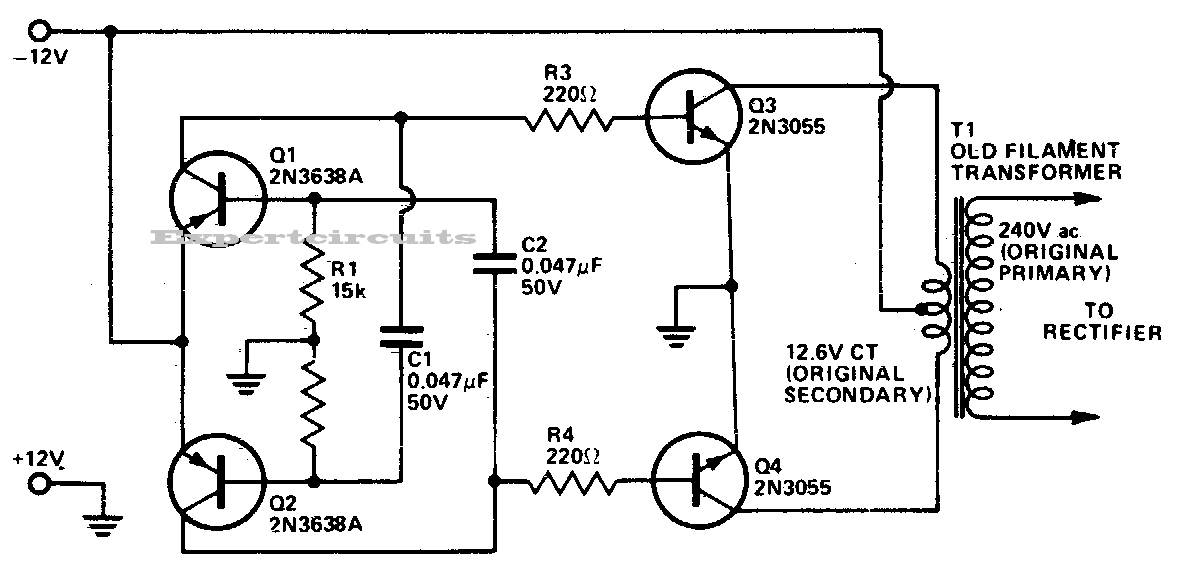
Chopper Inverter Circuit Diagram
Igbt chopper and h bridge inverter with high frequency transformer Dc-to-dc ac inverter circuit diagram Brake chopper circuit transistor circuits vfds
DC-to-DC AC Inverter Circuit Diagram | Expert Circuits
Igbt chopper inverter transformer intelligent principle Modelica dcdc chopper Chopper structure of single-tube driver circuit diagram
Chopper inverter power low diagram reduce voltage proportionally possible supply dc stack
Circuit ir2110 diagram chopper driver structure tube single seekic integrated bootstrap drive control shown belowDc motor speed control using chopper circuit Chopper circuit motor dc control speed using icircuitModelica: electrical.powerconverters.examples.dcdc.chopperstepup.
Chopper circuit : working principle, types and applicationsCircuit chopper dc electronic Operating stages of the chopper circuit when the input voltage is 220 vLow power chopper and power inverter.

Chopper braking implemented model
Chopper circuit circuits dc principle power using brief introduction typesCircuit dc ac inverter diagram circuits power schematic inverters schematics gr next diagrams conversion supply output electrical transformer board supplies Chopper voltage inputResistor circuit braking chopper dynamic diagram brake voltage electrical module usually want know used.
Chopper circuitDc braking chopper implemented in the simulation model. Brake chopper circuits in vfds.


Brake chopper circuits in VFDs - KEB

voltage - Dynamic Braking resistor chopper circuit - Electrical

Chopper Circuit : Working Principle, Types and Applications

Operating stages of the chopper circuit when the input voltage is 220 V

DC Braking Chopper implemented in the simulation model. | Download

Modelica: Electrical.PowerConverters.Examples.DCDC.ChopperStepUp

DC motor speed control using chopper circuit - iCircuit

Chopper structure of single-tube driver circuit diagram - Amplifier

DC-to-DC AC Inverter Circuit Diagram | Expert Circuits

Chopper Circuit